Wind Load Classification (AS 4055) for Prefab & Expandable Granny Flats: 2026 B2B Engineering & Tie-Down Guide (N1–N6 to C1–C4)
Compare AS 4055 wind classification N1–N6 and C1–C4 for prefab granny flats. Use the uplift example and factory checklist to prepare a site-specific RFQ.
Last Updated: October 29, 2026
Scope and limitations: English-language procurement guidance for global B2B buyers of prefab granny flat kits and expandable dwellings, using Australia as the engineering reference market. AS 4055 wind load classification identifies non-cyclonic N1–N6 or cyclonic C1–C4 site requirements; it does not certify a kit. This guide references AS 4055:2021 and AS/NZS 1170.2:2021, including applicable amendments. The project designer must confirm the NCC edition, referenced standards and state variations adopted for the permit location and date. Overseas wind codes require a separate local design. Use this article to prepare an RFQ and audit documents; obtain project-specific structural and geotechnical design before production.
Quick procurement answer: Obtain the site wind assessment first, then ask each supplier for the same deployed layout, design pressures, support reactions and connection drawings. Compare the complete roof-to-ground load path and supporting evidence, rather than a marketing wind-speed claim.
Method: The classification comparison is a procurement framework; the uplift calculation and AUD worksheet are reproducible hypothetical examples, not measured product performance, customer results or supplier quotations. Jimmy Su's author profile describes modular housing and logistics experience; project engineering remains the responsibility of appropriately qualified local practitioners.
For modular procurement, wind classification is not an optional accessory—it is the baseline structural load case that dictates chassis stiffness, connection detailing, and footing anchorage.
A supplier claim such as "heavy-duty steel" or "tested to 120 km/h wind" does not identify the installed building's design basis. For Australian secondary dwellings, ask the certifier to confirm the building classification and evidence required under the locally adopted NCC. NCC 2022 Volume Two, Part H1 provides a reference for structural reliability and glazing; its numbering is H1, rather than the older Part 2.2 terminology. A Queensland Form 15, where required, is design evidence for its stated scope, not a national product approval or installation certificate.
Expandable container homes and lightweight flat-pack kits combine a relatively large roof area with folding joints and low dead weight. Wind can act laterally, create roof suction and load an exposed subfloor. The installed mass, openings and support arrangement must come from the actual model's documents. If the design uplift exceeds stabilizing weight, the foundation and connections must resist the remaining tension; overturning and sliding require separate checks.
Before committing capital to overseas production runs, procurement teams must understand the physical mechanics of AS 4055 wind classes, calculate gross and net uplift forces, lock in factory bill of materials (BOM) upgrades, and enforce pre-shipment structural hold points.
Preparing an order for high-wind or coastal sites? Use our RFQ quote builder to submit the wind assessment, soil report and destination so the proposed structural scope can be reviewed before quotation.
Aerodynamic Physics: Why Lightweight Modular Units Experience Net Uplift
For an arithmetic comparison, velocity pressure follows q = 0.5 × rho × V². With assumed air density rho = 1.20 kg/m³, pressure in kPa is q = 0.0006 × V², where V is in m/s.
The relationship is quadratic. Holding all other factors constant:
- 40 to 50 m/s:
(50 / 40)² = 1.56, about 56% more velocity pressure. - 40 to 61 m/s:
(61 / 40)² = 2.33, about 133% more velocity pressure. - 40 to 74 m/s:
(74 / 40)² = 3.42, about 242% more velocity pressure.
Velocity pressure is not the design pressure on a window, roof fastener or anchor. The engineer must account for pressure coefficients, internal pressure, local zones, load combinations and the relevant component's tributary area under AS/NZS 1170.2.
ILLUSTRATIVE VELOCITY PRESSURE COMPARISON
========================================================================
Wind Class    ULS Gust (m/s)    Dynamic Pressure (kPa)   Load Multiplier
------------------------------------------------------------------------
N1               34 m/s                 0.69 kPa             0.72x
N2 (Base)        40 m/s                 0.96 kPa             1.00x (Baseline)
N3 / C1          50 m/s                 1.50 kPa             1.56x (+56%)
N4 / C2          61 m/s                 2.23 kPa             2.33x (+133%)
N5 / C3          74 m/s                 3.29 kPa             3.42x (+242%)
N6 / C4          86 m/s                 4.44 kPa             4.62x (+362%)
========================================================================
The Net Uplift Equation for Expandable Units
Consider a hypothetical deployed kit with these inputs:
- Projected roof area:
5.90 m × 6.30 m ≈ 37.2 m². - Dead weight G:
3,000 kg × 9.81 / 1,000 ≈ 29.4 kN. - Example velocity:
50 m/s, givingq = 1.50 kPa. - Assumed net uplift coefficient magnitude:
0.90, giving1.35 kPaover the example area. This is an input for illustration, not a conservative coefficient for every roof or opening condition.
Gross uplift W = area × assumed pressure
               = 37.2 × 1.35 = 50.22 kN
Illustrative net uplift = W − 0.9G
                        = 50.22 − (0.9 × 29.4)
                        = 23.76 kN ≈ 23.8 kN
The example uses 0.9G as stabilizing dead load; the project engineer must select the applicable AS/NZS 1170.0 load combinations and reliable installed mass. It shows why weight alone may be insufficient. 23.8 kN is a whole-building resultant, not an anchor rating. Do not divide it equally by the number of supports: eccentric loading, overturning, local uplift and frame stiffness can increase individual reactions. Request a support-by-support tension, compression and shear schedule before selecting footings.
Structural Mechanics & Load Paths in Folding Modular Envelopes
For expandable containers and flat-packs, audit the roof-to-wall, folding-joint, chassis and foundation interfaces. The diagram is a conceptual load path, not a fabrication or anchorage drawing.
Figure 1: Conceptual uplift load path for an expanded modular dwelling. Arrows show actions and required restraint; bracket geometry, reactions and footing capacity must come from the project design.
Critical Vulnerability Nodes in Prefab Assemblies
- Hinge Pins & Wing Restraint: Check both downward gravity loads and wind-induced load reversal. Require the deployed joint's pin, lock, bearing and weld details; a steel grade alone does not establish joint capacity.
- Roof-to-Wall Connections: Ask for the tested or calculated roof assembly, including panel profile, substrate thickness, fasteners, washers and edge-zone fixing pattern. Sheet pullover, screw withdrawal and cyclic performance are separate failure checks.
- Chassis-to-Foundation Connections: Require an uninterrupted tension and shear path through the chassis, bracket, anchor and footing. Leveling pads or friction contact do not demonstrate uplift or overturning resistance.
- Windows and Doors: Match the actual assembly size and installation to the project's SLS, ULS and water-penetration requirements under AS 2047. Neither glass thickness nor the velocity pressure in the table establishes a compliant window rating. Evaluate opening failure and internal pressurization in the building design.
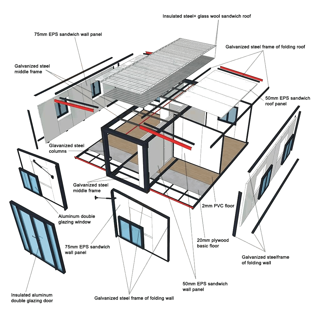
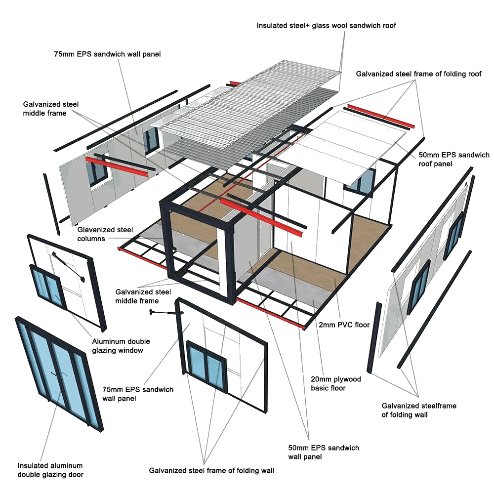 Figure 2: Exploded product illustration showing chassis, folding frames and panel interfaces. It identifies inspection locations; it is not evidence of a steel grade, tested wind class or certified assembly.
AS 4055 Wind Classification Matrix: Engineering Parameters & Procurement Actions
AS 4055 provides housing site wind classes within defined limits. The assessor considers wind region, terrain, topography and shielding, using the standard's assessment distances and rules. A postcode or an assumed 500 m circle is not a complete assessment. Region letters and site classes describe different things: a site in a cyclonic region is not automatically C2.
State variations also matter. For example, the linked NCC 2022 H1 provisions explain Western Australian variations affecting wind regions B/B2 and D. Have the assessor record the applicable regional map, variation and standard edition instead of assigning a class from a city name.
The matrix pairs commonly used ULS class speeds with calculated velocity pressures, rounded to two decimals using the formula above. The final column is an editorial document-review prompt, not an AS 4055 bill of materials. Confirm class speeds and separate SLS requirements against the project's adopted, amended standard.
| AS 4055 Wind Class | Wind Regime | ULS Class Speed (m/s) | Calculated Velocity Pressure (kPa) | Procurement Review Prompt |
|---|---|---|---|---|
| N1 | Non-cyclonic | 34 | 0.69 | Obtain the site assessment and a complete baseline connection schedule; do not assume anchorage is optional. |
| N2 | Non-cyclonic | 40 | 0.96 | Confirm the quoted model, openings and installed supports match the design documents. |
| N3 | Non-cyclonic | 50 | 1.50 | Ask for site-specific roof-zone pressures, window schedules and footing reactions. |
| N4 | Non-cyclonic | 61 | 2.23 | Review local connection demands and the deployed wing restraint details. |
| N5 | Non-cyclonic | 74 | 3.29 | Verify that every frame, panel and connection has evidence covering the calculated demands. |
| N6 | Non-cyclonic | 86 | 4.44 | Confirm the proposed modular system is feasible before committing to manufacture. |
| C1 | Cyclonic | 50 | 1.50 | Require cyclonic design evidence; equal class speed to N3 does not make the assemblies interchangeable. |
| C2 | Cyclonic | 61 | 2.23 | Review cyclic roof-fixing evidence, opening assumptions and the complete tie-down path. |
| C3 | Cyclonic | 74 | 3.29 | Agree on the footing verification and connection inspection plan before pricing. |
| C4 | Cyclonic | 86 | 4.44 | Obtain project acceptance of the entire building and foundation design before production. |
Reading the table: N3 and C1 share a class speed, but cyclonic cyclic-loading and opening/debris design conditions can differ. Neither a class label nor velocity pressure specifies bolt diameter, glass thickness, pile size or debris protection. Have the local designer identify the required evidence for each assembly.
Foundation Tie-Down Engineering: Screw Piles vs. Bored Concrete Piers
The Achilles heel of imported modular housing is the interface between the factory chassis and the ground. A factory cannot certify a complete building without knowing the foundation reaction capacity.
Compare foundation options against the same support reaction schedule, geotechnical report, durability exposure and installation constraints:
1. Helical Screw Piles with Bolted Chassis Brackets
Screw piles can avoid concrete curing delays where the ground and access suit the system.
- Capacity evidence: Require design tension, compression and lateral capacities for the actual soil profile, pile geometry, depth, corrosion allowance and group arrangement. Shaft diameter alone cannot establish uplift capacity.
- Connection: Match the pile head, chassis bracket, bolts and welds to the calculated reactions. Include eccentricity, hole tolerances and installation access in the drawings.
- Verification: Record installation depth and torque. Use torque-to-capacity correlation only where validated for the particular pile and soil; agree any proof-load testing and acceptance limits with the designer. Our screw piles vs concrete slab foundation guide provides a broader comparison; use project engineering for capacities.
2. Mass Concrete Bored Piers with Cast-In Anchor Rods
Where access, soil or rock conditions favor bored piers, ask the geotechnical and structural designers to establish depth, diameter, reinforcement and the applicable uplift failure mechanism.
- Resistance: The assessment may consider footing weight, soil resistance, groundwater, group effects and relevant resistance factors. A generic pier depth or assumed soil cone is not a capacity calculation.
- Connection: Specify the designed anchor system, embedment, edge distances, reinforcement, concrete strength and curing hold point. Check steel failure, concrete breakout and pull-out as well as the chassis bracket. Unverified sleeve anchors into loose masonry pads do not establish a continuous tie-down path.
3. Expandable Wing Ground Outriggers
Folding floor wings need a defined load path in their deployed position.
- Check whether the supplied screw-jack legs are rated only for compression and leveling. Do not count them as tension restraints without design evidence.
- The designer must determine whether wing-edge anchors, bracing, hinge locks or a combination carries uplift and lateral actions. Coordinate those requirements with the actual support plan rather than prescribing the same anchor layout for every wind class.
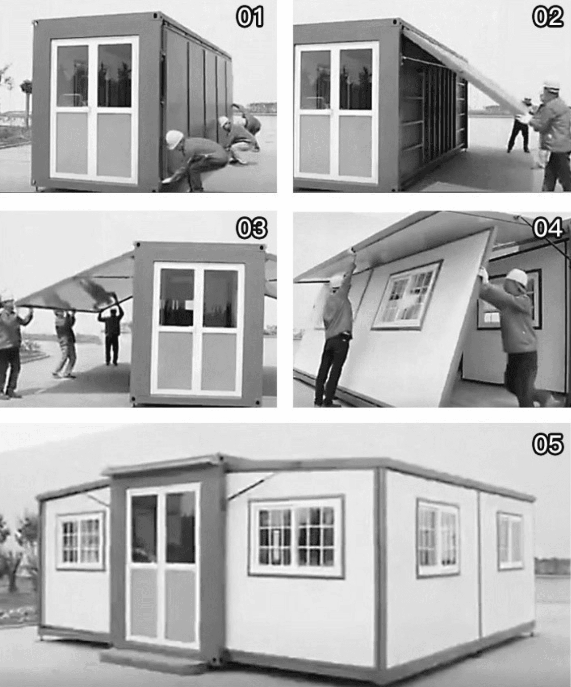 Figure 3: Product deployment sequence showing folding roof and wall interfaces. Review the installed restraints separately; the sequence does not demonstrate a wind rating or an approved installation method.
Cost Analysis: Factory BOM Delta vs. On-Site Remediation Penalty
Retrofitting an undocumented kit may require access work, replacement assemblies and fresh engineering. A factory change is worth pricing before production, but neither an upgrade budget nor a list of stronger materials guarantees acceptance.
The worksheet illustrates how to compare two hypothetical routes for one 38 m² kit: resolving an engineer-defined scope before manufacture, or rectifying it after delivery. All amounts are invented planning inputs in AUD, excluding GST; they are not market benchmarks or quotations. Freight, foundations, permits and delays are excluded. Replace every row with comparable written quotes for your destination and quantity; N3 and C1 require separate scopes.
| Structural Sub-System | Scope to Price Against Approved Design | Example Factory Delta (AUD) | Example On-Site Rectification (AUD) |
|---|---|---|---|
| Light Gauge Framing & Purlins | Price the specified sections, steel grades, thicknesses and bracing; allow for access to concealed members. | $650 | $5,500–$8,000 |
| Roof Sheeting & Cyclonic Fasteners | Price the documented panel and fixing system, including edge zones and any required cyclic test evidence. | $220 | $1,800–$2,800 |
| Hinge Locks & Wing Shear Pins | Price the designed pins, locks, welds and bearing details; require approval of material substitutions. | $380 | $3,200–$4,500 |
| Windows & Sliding Doors (AS 2047) | Price tested assemblies of the required size, pressure ratings and installation details. | $850 | $4,800–$7,200 |
| Chassis Hold-Down Bracket Pack | Price brackets, bolts and coatings matched to the footing reactions and corrosion exposure. | $250 | $1,400–$2,200 |
| Engineering Computations & Certificate | Price the defined design review and jurisdiction-specific documentation; identify testing charged separately. | $500 | $2,500–$4,500 |
| Total Financial Commitment | Cost comparison across single-unit procurement | $2,850 | $19,200–$29,200 |
Worksheet result: The six factory inputs sum to AUD $2,850; the on-site ranges sum to AUD $19,200–$29,200, or about 6.7–10.2 times the factory inputs. This arithmetic demonstrates the comparison method, not a saving forecast. Some systems cannot be economically retrofitted, and approval remains conditional on the completed design and installation.
For a comparable supplier response, send the reaction schedule and drawings with your engineering RFQ, and request separate lines for factory changes, local engineering, testing and foundations.
Global Procurement: AS 4055 vs. US ASCE 7-22 and Florida HVHZ
For global procurement, treat these as separate design briefs, not a wind-class conversion chart:
- Australia: Record the locally adopted NCC, referenced wind standard and amendments, site classification, opening assumptions and support reactions.
- United States, including Florida HVHZ: Ask the locally licensed designer and building authority to identify the adopted code/ASCE 7 edition, site wind parameters and product-approval or testing route. An AS 4055 C3/C4 label does not establish US or HVHZ compliance. Check whether each proposed approval covers the exact assembly, dimensions and installation.
- European destinations: Obtain the applicable national implementation of EN 1991-1-4, National Annex and local approval requirements before quoting structural changes.
A change from m/s to mph changes units only. Wind averaging conventions, return periods, exposure, pressure coefficients, internal pressures and resistance factors must be considered together by the destination designer. This article does not verify US or European code provisions or prescribe foreign design speeds.
B2B Factory Audit Checklist: 10-Point Pre-Shipment Structural Gate
Agree these hold points in the purchase order. The buyer's inspector should record drawing revisions, serial numbers, photographs, nonconformances and the designer's disposition before shipment release:
- 1. Steel Grade & Mill Certificates: Match heat/batch certificates to the grades and product standards in the approved member schedule. Verify substitutions with the designer. Use our G550 vs Q235 steel procurement guide for document-review context; grade alone does not prove wind capacity.
- 2. Base Metal Thickness: Check specified sections with calibrated equipment and an agreed method that distinguishes base metal from zinc and paint coatings. Record sampled locations and tolerances.
- 3. Hinges & Locks: Match pin material, diameter, retention, bearing and deployed locking details to the approved drawings. Stainless steel is not automatically a hardened or stronger substitute.
- 4. Roof Fixings: Match panel profile, substrate, screw type, washers and zone-specific spacing to the documented assembly and any required cyclic test evidence.
- 5. Window Evidence: Match labels and reports to each assembly's size, SLS/ULS ratings, water performance and installation schedule. Record separately any required debris protection and its evidence.
- 6. Chassis Tie-Downs: Check bracket dimensions, welds, holes, bolts and corrosion protection against the approved connection drawings and footing reactions. Record inaccessible inspection points before concealment.
- 7. Panel Assemblies: Check the specified skins, core, adhesive system and assembly identifiers. Refer suspected damage or delamination to the designer; visual inspection cannot establish bond or wind resistance.
- 8. Bracing: Confirm the installed straps, sheathing, hold-downs and connections match the lateral-load model, including around large openings and folding joints.
- 9. Fastener Traceability: Match bolt and screw grades, coatings, batch records and installation requirements to the connection schedule; reconcile supplied quantities with the packing list.
- 10. Design Dossier: Obtain calculations, pressure and reaction schedules, assembly instructions, inspection records and jurisdiction-specific design documents for the exact model and revision shipped. Assign responsibility for local footing and installation certification separately.
Frequently Asked Questions (FAQ)
Q1: Can an expandable container home be approved for a cyclonic site?
A: It may be feasible if the complete deployed system has suitable design evidence for the site and the certifier accepts the proposed pathway. Confirm the site class, roof and wall assemblies, openings, folding joints and foundation reactions before ordering. Do not assume an undocumented export kit is N1/N2-rated or that a fixed upgrade list guarantees approval. Region C is a regional designation; C2 is a site class.
Q2: What is the difference between AS 4055 and AS/NZS 1170.2?
A: AS 4055 provides housing wind classes within its scope; AS/NZS 1170.2 provides a broader wind-action procedure. NCC 2022 H1's AS 4055 explanation lists limits including eaves height 6 m, roof height 8.5 m, width 16 m, length five times width and roof pitch 35°. Those dimensions alone do not establish applicability: the designer must check the complete scope and the deployed geometry, including wings and openings. Where the simplified procedure is unsuitable, obtain an appropriate engineered wind-action assessment.
Q3: Why does our private certifier reject our imported kit's ISO 9001 and CE certificates?
A: Neither establishes site-specific Australian structural compliance by itself. Ask for the certificate's exact scope and the building system's design and test evidence. The certifier should identify the applicable NCC evidence pathway and any local professional-registration requirements; RPEQ registration and professional credentials such as NER/CPEng are not interchangeable nationwide approval documents.
Q4: How do we test helical screw piles to prove they will withstand cyclonic uplift forces?
A: Have the designer set a verification plan for the soil, pile system and required reactions. It may combine validated installation-torque correlation with static tension testing. Record pile geometry, depth, installation data, test loads, displacement and acceptance criteria. There is no universal torque factor, test percentage or displacement limit supplied by this guide; distinguish ultimate resistance from factored design capacity.
Q5: Can we use concrete ballast blocks instead of drilling ground anchors or screw piles?
A: Only as a designed ballast system. For a weight-only illustration, concrete density of 2,400 kg/m³ and a 0.9 stabilizing factor give 30 / (0.9 × 2,400 × 9.81 / 1,000) ≈ 1.42 m³ to counter a 30 kN uplift resultant. That is not an approved ballast volume: overturning, sliding, buoyancy, bearing, attachment and individual support reactions can govern. Compare designed ballast, piles and piers using site-specific costs and constraints.
Strategic Next Steps: De-Risking Modular Procurement
Procuring wind-rated granny flat kits successfully requires establishing clear contractual hold points between the overseas manufacturer, the importer, and the local certifier:
- Conduct the Site Wind Assessment First: Obtain an assessment from a practitioner competent and authorized for the jurisdiction. Record the location, regional map, terrain, topography, shielding, standard edition and resulting class or engineered pressures.
- Embed the Design Basis in the Purchase Order: Include the class or pressures, deployed layout, opening schedule, member/material specifications, footing reactions, connection drawings and responsibility for local design review. AS/NZS 4600 is a cold-formed steel design standard, not a steel grade.
- Require Stamped Engineering Before Production: Make manufacturing commencement conditional upon receipt of certified structural computations and footing reaction schedules signed by a qualified structural engineer.
- Enforce Pre-Shipment Inspection: Utilize a third-party inspector to execute the 10-point structural gate checklist, verifying steel micrometer gauges, hinge pins, and fastener specifications before the shipping container leaves the factory gate.
Factory Specifications & Engineering Support
Discuss the proposed model, destination and required engineering evidence with GrannyFlatKits before fixing the procurement scope.
- Review layout options and structural framing across our complete granny flat product range.
- Review the evidence to request on our compliance documentation page.
- Submit your site wind assessment, soil test and floor plan through the online RFQ quote builder, or contact our B2B trade specialists, to clarify the factory package, local engineering scope and exclusions before quotation.
Sources & Technical References
- Standards Australia — AS 4055:2021 catalogue: Wind loads for housing. The public record confirms its housing-classification scope and lists Amendment 1:2024. Use the adopted amended text for a project assessment.
- Standards Australia — AS/NZS 1170.2:2021 catalogue: Structural design actions, Part 2: Wind actions. The record describes wind-action procedures, to be read with AS/NZS 1170.0, and lists Amendment 2:2024.
- ABCB — NCC 2022 Volume Two, Part H1 Structure: H1P1 addresses structural reliability; H1D8 covers glazing and explains AS 4055 geometry. Its state variations demonstrate why local adoption must be checked. This edition is a reference, not a claim that NCC 2022 governs every 2026 permit.
- James Cook University — Cyclone Testing Station: Applied research, industry consulting and testing resources for severe-weather effects on low-rise buildings. This is a resource directory, not a test report for a GrannyFlatKits model.
- Standards Australia — AS 2047:2014 catalogue: Windows and external glazed doors in buildings. The record describes assembly requirements and lists Amendment 2:2017; its status was "Pending Revision" when checked.
Link and catalogue checks: October 29, 2026. Public catalogue records confirm identity, scope and listed amendments; full paid standards and project certifications were not independently reviewed. Recheck before each procurement and when code adoption or standards change; review this guide at least annually.
Author

Categories
More Posts

EPS vs PU vs Rockwool Wall Panels in Prefab Granny Flats: 2026 Procurement Guide
Compare EPS, PU/PIR, and Rockwool wall panels for prefab granny flat kits. Check fire, R-value, freight, and compliance questions before you quote.
Australia Granny Flat Approval Checklist (2026)
Australia granny flat approval checklist (2026) — a practical pre-quote guide covering council approval, CDC vs DA pathways, site constraints, and compliance steps before buying a granny flat kit.
Light Gauge Steel (LGS) in Prefab Granny Flats: G550 vs Q235 Procurement Guide 2026
Discover the critical differences between G550 high-tensile steel and Q235 mild steel in prefab granny flats. Learn how to verify yield strength and coatings.